Engineering Dropper Cables: Torsion, Heat, Pre-Termination
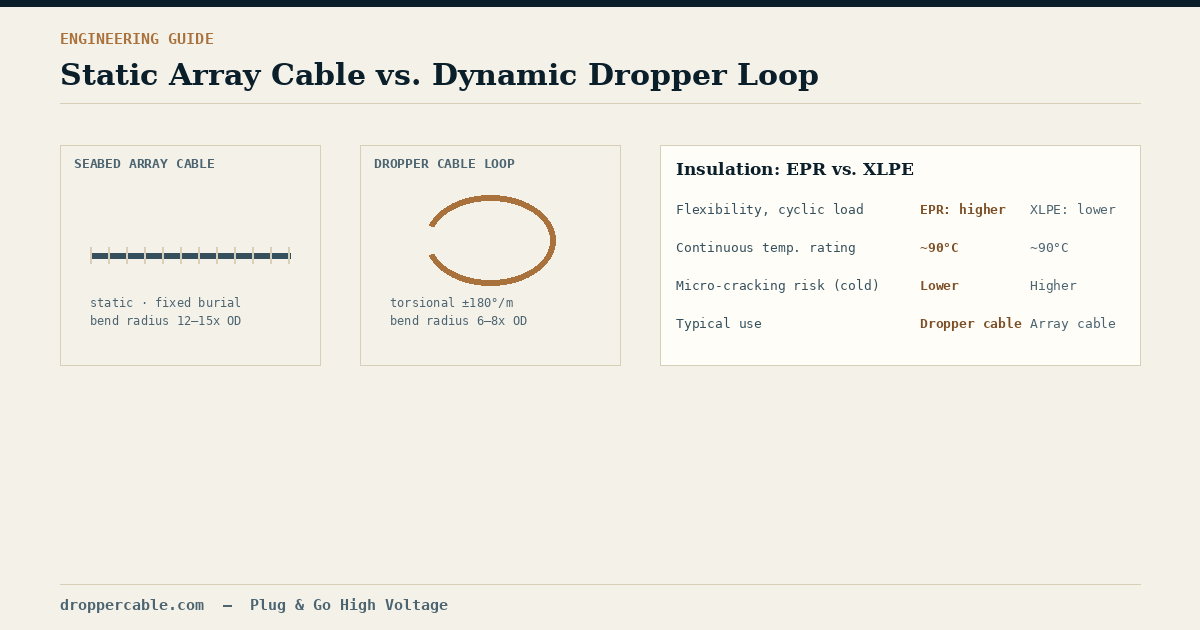
Most of a wind farm’s cabling sits still. Inter-array cables are trenched or rock-dumped into the seabed and, once installed, experience only gentle thermal cycling for the rest of their service life. The dropper cable is the exception. It hangs in a loop between the yawing nacelle and the tower-base switchgear, and every time the turbine’s control system rotates the nacelle to track wind direction, that loop twists.
This single difference — motion versus stillness — drives almost every design decision that separates a dropper cable from a standard distribution cable. It’s worth understanding in more depth than “it needs to be flexible.”
Torsion Is the Design-Governing Load
A fixed seabed cable is engineered primarily around burial stress, crush resistance, and a generous bend radius applied once, during installation — typically in the range of 12 to 15 times the cable’s outer diameter, and never revisited. A dropper cable’s upper loop, by contrast, is engineered around cyclical torsional rotation applied thousands of times over a 25-plus-year service life, with a correspondingly tighter dynamic bend radius, often in the 6 to 8 times outer diameter range, because the cable has to physically fit and flex within a constrained tower or transition-piece cross-section.
That repeated twisting is what drives conductor design. A standard rigid concentric-lay copper conductor will birdcage — the outer strand layer buckles outward — under sustained torsional load. Dropper cables instead use fine-stranded, flexible conductor construction (commonly Class 5 or Class 6 stranding) with low-friction separator layers between strand layers, letting individual wires move relative to one another as the cable twists rather than fighting the rotation as a rigid unit. The outer sheath matters too: high-tear, abrasion- and torsion-resistant polyurethane or thermoplastic elastomer jacketing is standard, chosen specifically to survive contact with tower guide saddles and cable cleats over years of yaw cycling rather than for chemical resistance alone, which is the priority for a buried cable’s outer layer.
EPR vs. XLPE: Why the Internal Cable Often Isn’t XLPE
Cross-linked polyethylene (XLPE) dominates fixed subsea array cable insulation because of its low dielectric losses and strong long-term performance under continuous, largely static loading. Inside the tower, though, many dropper cable specifications favor ethylene propylene rubber (EPR) instead, and the reason comes back to motion again. XLPE is a semi-crystalline thermoplastic that can develop micro-cracking when repeatedly flexed and twisted at lower temperatures. EPR is an elastomer instead, which makes it inherently more tolerant of cyclical mechanical deformation without losing dielectric integrity. EPR also handles thermal cycling well — rated for roughly 90°C continuous conductor temperature with short-circuit withstand well above that — which matters in a densely packed, often poorly ventilated upper tower section where several current-carrying cables sit close together.
Neither material is universally “better”; XLPE remains the right call for a cable that will be buried once and left alone. The distinction is that dropper cable specifications are solving a different mechanical problem than array cable specifications, even though both may operate at similar voltage classes. We’ve covered separately why more projects are specifying 66kV rather than 33kV for the array side of this equation. That same voltage-class shift raises the electrical stress at every dropper cable termination point too — which is why insulation choice at the connector interface deserves as much attention as insulation choice along the cable run.
Pre-Termination: Moving the Riskiest Step Off the Tower
Stripping and terminating medium-to-high-voltage EPR insulation — building up stress control geometry, fitting a separable connector body, applying pressure correctly — is precision work. Doing it inside a turbine tower, in variable humidity, with limited working space and a vessel clock running, is where field joints have historically gone wrong: a contamination particle trapped under a stress cone, or a termination assembled slightly out of tolerance, doesn’t usually fail on day one. It fails months later, as a partial discharge site that slowly degrades the insulation until it doesn’t.
Factory pre-termination addresses this by moving that step into a controlled environment and testing the result before the cable ever leaves the factory — we’ve broken down the cost and schedule case for that shift separately, including where field jointing still makes sense. Under IEC 60840, a properly manufactured and terminated HV cable assembly should show no detectable partial discharge above the test instrument’s background noise floor — typically held to a limit under 5 picocoulombs (pC) at the specified test voltage. An assembly that passes that test at the factory, with a plug-in separable connector already fitted, arrives on site ready to be hoisted into position and mated to the switchgear bushing directly, with no stripping, no on-site stress cone assembly, and no weather-dependent termination work standing between delivery and commissioning.
The Practical Upshot
None of this is exotic engineering — it’s a direct consequence of one component being asked to move while everything else on the cable side of the project stays still. For procurement and engineering teams, the useful question to ask a supplier isn’t “is it rated for the voltage.” It’s whether the conductor stranding, insulation material, and connector system were actually selected for dynamic torsional service — and whether the completed assembly is partial-discharge tested before shipping, rather than tested to a lower internal standard, or not meaningfully tested at all. Reynard builds preassembled dropper cable and connector systems around exactly this distinction, with each assembly factory-tested before it leaves for the vessel — the kind of detail that’s easy to overlook on a datasheet and expensive to discover offshore.