Dropper Cable Failure Modes: A Root Cause Reference
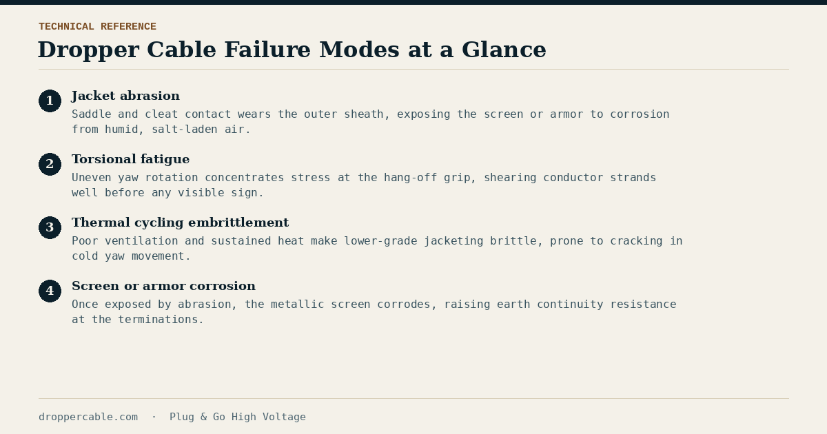
Most dropper cable failures trace back to one of a small number of root causes, and nearly all of them are mechanical in origin even though the symptom that eventually surfaces is electrical — a tripped relay, a partial discharge alarm, or worse. Knowing which mechanism is at work changes what an inspection should actually look for.
Jacket Abrasion
As the nacelle yaws, the dropper cable’s dynamic loop rubs against guide saddles and cable cleats designed to control, not eliminate, contact. Repeated rubbing wears through the outer sheath, and once the metallic screen or armor underneath is exposed to humid, salt-laden air inside the tower, corrosion follows — usually well before it’s visible without a close inspection near every support point.
Torsional Fatigue
Wind direction isn’t evenly distributed at most sites, so a turbine’s yaw system tends to accumulate rotation in a dominant direction over a season before correcting. That uneven rotation concentrates torsional stress at the top hang-off grip rather than spreading it along the loop. In conductor stranding not specified for genuine dynamic service, individual strands can shear at that point, creating a localized hot spot long before there’s any visible external sign of damage.
Thermal Cycling Embrittlement
Upper tower sections are often poorly ventilated, and several current-carrying cables running close together generate real heat under full load. Lower-grade jacketing that bakes under sustained thermal load turns brittle over time, and brittle sheath material is far more prone to cracking during the low-temperature yaw movements of a winter storm than the same material was when new.
Screen or Armor Corrosion
Corrosion is usually a second-order failure mode — it follows jacket abrasion rather than starting independently, since the metallic screen or armor is what actually corrodes once exposed. Rising resistance in an earth continuity measurement at either end of the cable is often the earliest instrumented sign, showing up before any visible external damage does.
Using This as a Diagnostic Reference
None of these four failure modes require exotic diagnostics to catch early. A thermal scan under load, a visual check at every support point, and an earth continuity measurement at both ends cover most of what’s described here — the detail is in our full inspection checklist, which walks through the practical routine these root causes point back to.