Inspecting and Replacing Offshore Wind Dropper Cables
Offshore wind operations teams spend a lot of scheduled maintenance time on gearboxes, pitch bearings, and main bearings — components with well-documented failure curves and expensive consequences. Dropper cables get comparatively little attention, largely because they have no moving parts of their own. That’s also exactly why problems go unnoticed until they show up as an electrical fault: a tripped protection relay, a partial discharge alarm, or in the worst case an arc flash event inside the tower, all of which cost far more in downtime and vessel mobilization than a scheduled cable inspection would have.
Three Failure Modes Worth Knowing
For a fuller root-cause breakdown of these and a fourth related mode, see our dropper cable failure modes reference.
Jacket abrasion from tower saddle contact. As the nacelle yaws, the dropper cable’s dynamic loop moves against guide saddles and cable cleats designed to control, not eliminate, contact. Repeated rubbing wears through the outer sheath over years of operation, and once the metallic screen or armor beneath is exposed to the humid, salt-laden air inside an offshore tower, localized corrosion follows — often well before it’s visible without a close inspection.
Torsional fatigue at the hang-off point. Wind direction isn’t evenly distributed at most sites; a turbine’s yaw system tends to accumulate rotation in a dominant direction over a prevailing-wind season before correcting. That uneven rotation concentrates torsional stress at the top hang-off grip specifically, rather than distributing it evenly along the loop. In a cable whose conductor stranding wasn’t specified for genuine dynamic service, individual strands can shear at that point, creating a localized hot spot long before there’s any visible external sign of damage.
Thermal cycling embrittlement. Upper tower sections are often poorly ventilated, and multiple current-carrying cables running close together generate meaningful heat under full load. Lower-grade jacketing that bakes under sustained thermal load can turn brittle, and brittle sheath material is far more prone to cracking during the low-temperature yaw movements of a winter storm than the same material was when new.
A Practical Inspection Checklist
During scheduled balance-of-plant maintenance, a dropper cable check doesn’t need specialized tooling beyond what most offshore techs already carry:
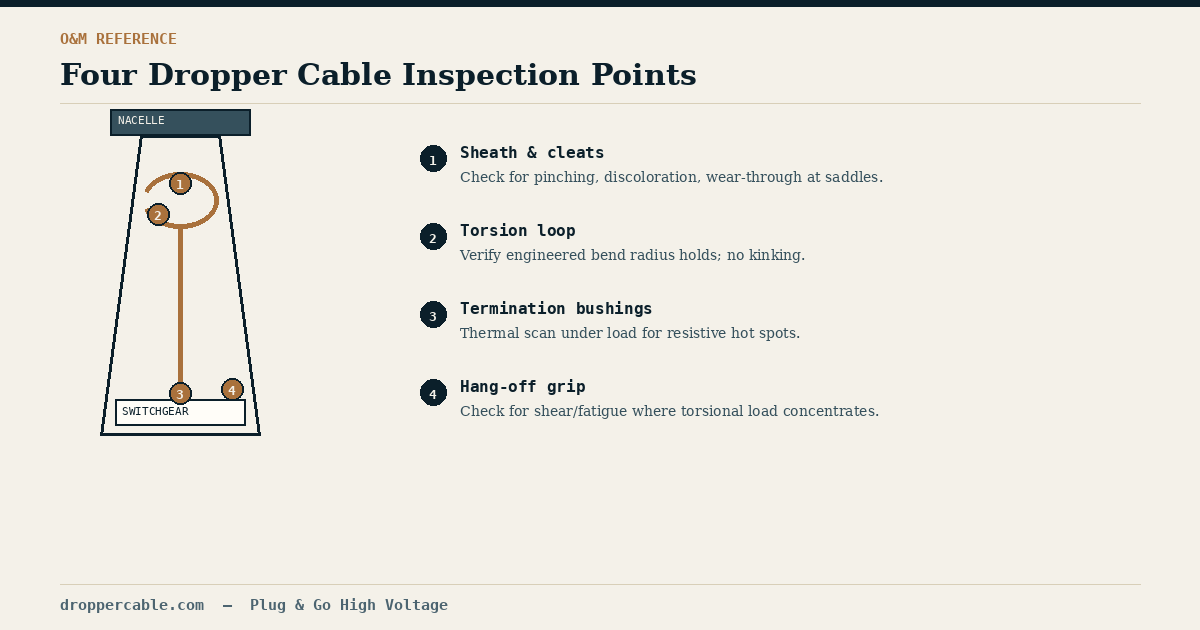
Visually audit the sheath near every support cleat and saddle for pinching, discoloration, or visible wear-through. Check that the dynamic torsion loop still holds its engineered bend radius without kinking or flattening. Run a thermal imaging scan across termination bushings and the hang-off grip under load, since a resistive hot spot will usually show up thermally before it shows up any other way. Where online partial discharge monitoring is available, use it to catch insulation voids developing inside the cable before they progress to failure. And measure screen or armor earth continuity at both ends — a rising resistance reading is often the earliest indicator of the corrosion described above.
None of these are exotic tests. The value is in doing them on a schedule, because dropper cable degradation is progressive and inspectable well before it’s an emergency.
When Replacement Is Faster Than Field Repair
If an inspection turns up serious degradation, the instinct to repair in place is usually the wrong one. Splicing or re-terminating a medium-to-high-voltage cable inside a tight tower base is slow, weather-dependent, and reintroduces exactly the field-jointing risk we’ve written about in the context of new installations — except now it’s happening on an aging, already-stressed cable rather than a new one.
A pre-terminated replacement kit, cut to the exact tower dimensions with connectors already fitted and factory tested at both ends, turns what could be a week-plus outage into a matter of hours: hoist the assembly up through the tower using its integrated pulling eye, plug it into the switchgear, and return the turbine to service. The engineering upside of factory pre-termination that applies to new builds — no on-site stripping, no weather-dependent termination work, guaranteed test data before the cable ever ships — applies just as directly, and arguably more urgently, to emergency and planned replacement work where every day of downtime has a clear cost attached.
Building Replacement Into the Maintenance Plan
Asset managers who treat dropper cables as a scheduled wear item, rather than something that’s only addressed after a fault trips offline, tend to spend meaningfully less on emergency vessel mobilizations over an asset’s life. Reynard supplies pre-terminated dropper cable replacement assemblies built to exact tower dimensions and tested before shipping, for operators who’d rather plan a swap than schedule an outage.